
Continuous Tablet Manufacturing, Step by Step: From Raw Material to Coated Tablet
ICH Q13 wrote down the rules in 2022 and worked through an example tablet line. This walks that line in order, from the drum on the loading dock to the coated tablet, and shows which steps are already continuous in most plants.





What “Continuous” Means to a Regulator
Continuous manufacturing stopped being a regulatory question in November 2022, when ICH Q13 reached Step 4 and was adopted by FDA, EMA, PMDA and the rest of the ICH membership. The guideline covers drug substances and drug products, new molecules and generics, and the conversion of an existing batch process to continuous. For a plant weighing the move, the useful thing is that the expectations are now written in one place.
Three of its definitions change how a line is designed. First, a batch is no longer a kettle’s worth of material. It can be defined by a quantity of output, a quantity of input, or a run time at a defined mass flow rate, and the batch size can be filed as a range. Q13’s own tablet example runs batches anywhere between 360 and 1,080 kg off the same equipment, by changing nothing but the run time. Second, a line does not have to be continuous end to end. Q13 names the hybrid mode explicitly: some unit operations continuous, others batch, with surge hoppers between them to absorb the difference in rates. Third, a state of control does not mean steady state. Parameters are allowed to move within their ranges, which is what makes start-up, shutdown and the occasional disturbance normal events rather than deviations.
Around those definitions sit three working ideas that every section below comes back to. Residence time distribution (RTD) is how long material spends in a process step and how much it spreads out in time while it is there. It is measured with a tracer that flows like the API, and it is what lets you trace an input lot through the line. Material diversion is the planned removal of off-spec material in real time: the criteria that trigger it, the amount removed (set by the RTD), and the conditions for collecting product again. Diverting during a planned start-up or shutdown needs no investigation as long as the preset criteria are met. And process analytical technology (PAT) is the measurement that makes the first two possible, usually an NIR probe reading the blend as it moves.
One point is easy to miss. Roller compaction, milling and tableting already run as continuous or near-continuous operations in most plants, and the industry’s own facility design guides treat them that way. Many plants have been running continuous steps for years without calling them that. The question is rarely whether to go continuous; it is which handoffs between the steps still run as batch, and whether that is by design or by accident.
Q13’s Annex II works through an example tablet line: loss-in-weight feeders, a continuous blender, a tablet press with an NIR probe in the feed frame and a diversion point after it, and film coating in batch mode. The rest of this article follows that line in order, step by step.
Step 1: Raw Material In
A continuous line is unforgiving about what it is fed. Annex II identifies two incoming material attributes as critical to blend and content uniformity: the bulk density of the primary excipient and the particle size distribution of the API. Both got specifications of their own in the example, a density range for the excipient and a three-point d10, d50, d90 PSD for the drug substance. In a batch process a lot that is slightly off gets blended for a few more minutes. In a continuous process it goes straight into the feeder and shows up downstream within the blender’s residence time.
So the first step is to protect the line from what arrives in the drum. Three jobs happen here.
Check screening at the entry points
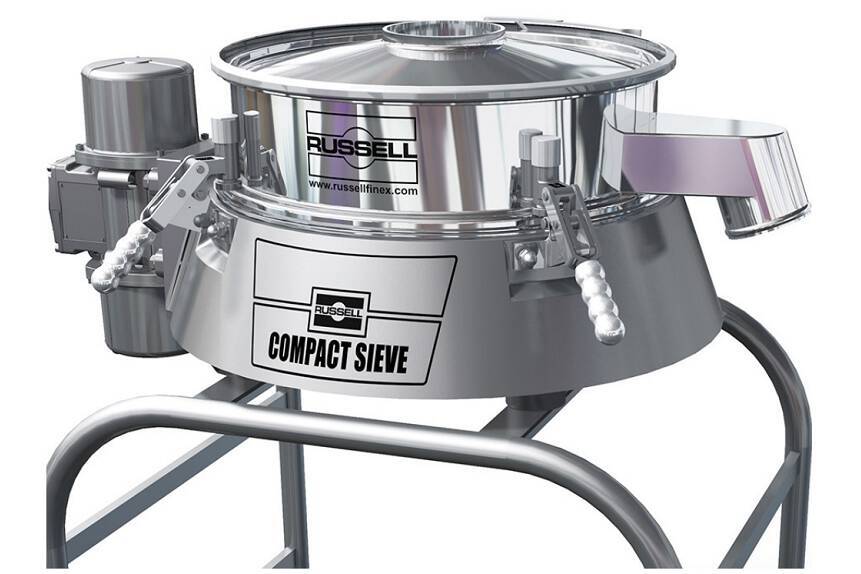
Foreign material caught after compression is a tablet lot; foreign material caught at the drum is a sieve change. Russell Finex positions check screening at the point of entry as a quality control step rather than clean-up, and their equipment is built to make that step repeatable: the Compact Sieve fits in less than half the height of a traditional screener, tool-free clamps let the mesh come out for inspection inside a changeover window, and the DQ/IQ/OQ/PQ documentation package gives the step a validated footing in the control strategy. Where the material is already moving in a vacuum conveying line, the airswept version screens inside the line, so the checkpoint adds no open handling.
Delumping before feeding
Excipients and APIs form lumps in storage and in transit, and a lump that reaches a loss-in-weight feeder arrives as a pulse in mass flow. Conditioning the material before it is fed takes that disturbance out of the line before the control strategy has to deal with it. Frewitt conical sieve mills deagglomerate and calibrate incoming material at production rates up to 2,500 kg/h, and the same machine base takes interchangeable heads with automatic head detection, so the mill set up for delumping can also serve as the inline granule mill later in the line. Stored formulas and 21 CFR Part 11 records in the control module mean the step produces data the filing can use, not a logbook beside it.
Contained discharge for potent APIs
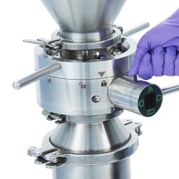
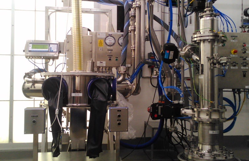
When the API is potent, the drum or IBC discharge is the line’s first exposure point, and a continuous line runs it far more often than a batch line does. The two ways we handle it are not alternatives so much as answers to different questions. A split butterfly valve from ChargePoint closes the connection itself: the active half on the process side and the passive half on the container mate, open together and separate clean, with validated containment from 1 µg/m³ down to 0.1 µg/m³ and below depending on the model. A contained discharge station from DEC closes the operation: the DCS drum containment system is a glove box built around the drum, so emptying, inverting a lumpy drum, and sampling an incoming lot all happen without the operator reaching the powder. Many lines use both, a valve on every container connection and a station where the drum has to be opened.
Step 2: Feeding
Each ingredient in a continuous direct compression line gets its own loss-in-weight feeder, which meters material by mass and adjusts its screw speed to hold the set flow rate. The feeders are the first continuous unit operation and, in Q13’s own words, the source of the fast disturbances the control strategy has to handle. Annex II characterised the mass flow rate and its variability for every feeder, set proven acceptable ranges by design of experiment, and defined limits on the size and duration of a flow disturbance beyond which material is diverted, an operator investigates, or the line stops.
The weak spot is named in the guideline. A feeder works gravimetrically, weighing its own hopper and adjusting, except while that hopper is being refilled, when it falls back to volumetric control until the scale settles. Q13 asks for the duration and mass of each refill to be evaluated and minimised. The practical answer is to refill often, in small amounts, from a sealed source, so the feeder spends as little time blind as possible and nothing enters the material path by hand.
That is a vacuum transfer job. The DEC PTS Powder Transfer System moves powder through sealed tubing in alternating vacuum and pressure cycles, refilling a feeder hopper from a drum, an IBC or a silo on demand, without gravity and so without the mezzanine, and fully contained below 1 µg/m³. With a PLC panel it supports recipe control and scale integration, which is what makes a refill a controlled event in the data rather than a bump in the trend. For a feed that itself has to be continuous, DEC’s Powderflex alternates two small calibrated chambers at high frequency to deliver a practically continuous flow at 1 to 2 percent dosing precision, from a few hundred grams per hour to 200 kg/h.

Step 3: Continuous Blending
The feeders discharge into a continuous blender, in Annex II a horizontal unit with paddles rather than a ribbon. The example treated the blender design itself as critical: paddle count, paddle orientation and rotation speed were all studied for their effect on blend uniformity, and the ranges that worked became the design space for the step.
The blender is also where RTD does its most visible work. A continuous blender mixes forward and backward along its length, and the RTD describes how much. That number sets two things the filing has to state: how far a feeder upset spreads before it reaches the press, which is the traceability question, and how much material has to be diverted after the upset to be sure none of it reached the tablets. The RTD is measured by running a tracer with the API’s flow properties through the system and watching it arrive. Downstream, the same measurement fixes where the diversion gate has to sit.
There is a second way to blend in a line, and it uses the same vacuum transfer that refills the feeders. DEC’s PTS Batchmixer has no rotating drum and no impeller. A PTS unit sits on top of the mixing container with two tangential inlets, draws the ingredients in by suction, and circulates the powder through the container past a central deflector until the blend is homogeneous, at better than 0.1 percent RSD and at mix ratios up to 1 to 10,000. Because the mixer fills itself and discharges completely, it drops into a line between the feeders and the press as a self-loading, self-emptying blending step with no open transfers on either side. A Powderflex can inject a minor ingredient continuously into the circulation line during mixing, and a spectrometer in the same circulation line validates the blend in real time, so the step produces the PAT data the control strategy wants without a sample leaving the system. It runs contained to OEB 4 and 5, inert for oxygen-sensitive materials, and CIP and SIP in place.

Step 4: The Route Choice, Direct Compression or Dry Granulation
Direct compression is the shortest continuous route: feed, blend, press. It works when the blend flows and compresses well enough on its own, and a large share of continuous lines filed so far take it. When a formulation does not flow, or the API dose is high and the blend will not compress, the line needs a granulation step between blending and the press. Twin-screw wet granulation with a continuous dryer is one way to add it. Dry granulation by roller compaction is the other, and it has the advantage of being continuous by nature.
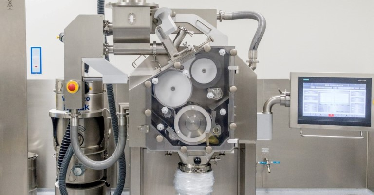
A roller compactor draws powder between two counter-rotating rolls, densifies it into a ribbon, and mills the ribbon into granules in one pass. Powder in, granules out, for as long as the feed lasts, with no liquid and no drying step to batch the process around. Gerteis compactors hold press force constant by letting the gap between the rolls float with the powder supply, so a fluctuation in feed becomes a small movement in gap rather than a swing in force, and ribbon density, the property that governs granule size, flow and compressibility downstream, stays where it was set. Force, gap and roll speed are measured on-line with calibrated instrumentation and held under closed-loop control, which is the PAT and QbD footing Q13 expects a continuous unit operation to have.
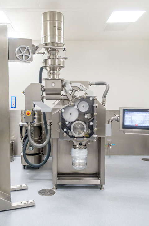
The newest piece takes the last offline measurement inside the machine. Gerteis’ Inline Density Control, an add-on for the PACTOR® series, measures ribbon density continuously at the outlet and adjusts press force to hold the target, without stopping production and without product-specific calibration. Scale-up matters too, because Q13 asks for the control strategy and RTD to be reassessed whenever equipment changes. The Mini-Pactor® and Macro-Pactor® share the same roll geometry and the same process settings, so a process developed on the small machine moves to the production machine without a new RTD study. The residence time inside a compactor is seconds, and material loss at start-up and shutdown is under 1 percent, so the diversion strategy for this step is about as simple as a continuous step can have.
The integrated granulator sizes the ribbon as it leaves the rolls, the last stage inside the same machine. Where the formulation needs a second sizing pass, or a different mill geometry, a Frewitt mill runs inline between the compactor and the final blend. Milling is a continuous operation in its own right, and Q13’s Annex IV example places it exactly there, between granulation and compression.

Step 5: Watching the Blend: PAT, RTD and Diversion
This step has no equipment of ours in it, and it is the heart of a Q13 filing, so it deserves a plain description. In Annex II, an NIR probe sits in the tablet press feed frame, reading the blend a few seconds before it is compressed. The probe location and height are fixed, the effect of material build-up on the window was studied and found insignificant, and the NIR method was developed, calibrated and validated on the commercial system itself, not on a lab rig.
Two residence time distributions connect the probe to the rest of the line. The RTD from the feeders to the probe tells the system how long after a feeder disturbance the blend at the probe will show it. The RTD from the probe to the diversion point, measured with a tracer, tells it how long after an off-spec reading the affected material reaches the gate. The diversion strategy ties the feeder limits and the NIR limits to those two numbers, with a safety margin for measurement uncertainty, so that every tablet made from a disturbed segment of blend is removed and nothing good is thrown away with it.
Real-time release testing follows naturally from this much in-line data, and Q13 explicitly allows it, but it is not required. A line can file a conventional end-of-batch release and still run continuously. What is required is the control strategy: the measurements, the limits, the RTDs and the diversion logic, documented in the CTD at the sections Q13 lists.
Step 6: Compression
The press is the step most plants already run continuously without thinking of it that way. Blend goes in at the top, tablets come out at the bottom, and the machine runs for as long as the feed frame is full. In a continuous line it gains two things: the NIR probe in the feed frame described above, and active process control of tablet weight, with compression force feeding back to the fill depth so that weight holds through small changes in blend density.
What changes around the press is how it is fed. On a continuous line, the press hopper is one more buffer that has to be refilled faster than it empties, and the same PTS vacuum transfer that refills the feeders can refill it, from the blender outlet or a surge hopper, without an operator and a bin at the top of the machine. Containment at the press itself is the press maker’s job, and the continuous line changes nothing about that; what it changes is how often the hopper is topped up, which is why the refill should be a sealed transfer.
Step 7: Dedusting and Transfer to the Coater
Here is the handoff that Annex II spells out and most line diagrams skip. In the example, the coater holds one hour of production. Coating takes 45 minutes, and while it runs, the next hour of tablet cores is collected in the coater’s tablet hopper. That transfer repeats every hour, around the clock, for the whole run. In a batch plant it is a bin on a lift. In a continuous plant it is a unit operation of its own, and the tablets going through it are at their most fragile: freshly compressed, uncoated, with edges that chip in a drop chute and dust that has to be removed before coating.
DEC’s TCS Tablet Conveying System moves tablets and capsules by vacuum from the press to the coater. A shaped hopper and inlet flap guide the tablets into the body without a shock, and a spiral ramp inside slows them gradually by inertia loss so they arrive spaced out and never collide. The conveying speed adjusts to the tablet’s size, shape and fragility, a window in the top lets an operator watch the transfer, and pre-dedusting is built into the unit and linked to the plant’s external filtration, so the cores arrive at the coater already dedusted. The body is electropolished 316L and CIP cleanable. It is rated for transfer between a tablet press, a coater, a capsule filler, a blister line and storage, which covers every tablet handoff downstream of compression.
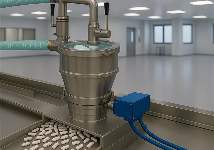
Dedusting itself is not a cosmetic step. Russell Finex’s guide to contamination prevention in manufacturing names tablet dedusting after compression as an in-process GMP checkpoint, in the same category as check screening the incoming API, and the point stands whoever builds the equipment. A metal check on the tablet stream belongs in the same place, after dedusting and before the coater, where a reject still costs a handful of cores rather than a coated lot.
Step 8: Coating
Annex II coats in batches, and that is worth pausing on, because it makes the example a hybrid line by Q13’s own definition. The feeders, blender and press run continuously; the coater runs one-hour loads with a tablet hopper as the buffer in between. Q13 does not treat that as a compromise. A hybrid line with a well-characterised buffer is a legitimate end state, and for most plants it is the sensible one, since the coater is often shared across products and already sized for the campaign.
Fully continuous coaters exist, with the tablet bed moving through the pan at a controlled rate rather than tumbling as a fixed load, and a line that needs its batch defined entirely by run time with no hourly buffer can use one. Either way, the coater is where the batch record closes, and the RTD of everything upstream is what lets that record say which input lots are in which coated tablets.
Walking the Line as One System
Every step above has a manufacturer that builds it well. The line is the chain of handoffs between them, and the handoffs belong to nobody’s catalogue. When a continuous project comes to us, the working method is to walk the line from the loading dock to the coater with the customer and classify every transition as one of three things.
- Manual transitions are engineered out first. A drum tipped into an open hopper is a containment gap, a dust source and a feed pulse in one, and on a continuous line it happens dozens of times a shift instead of once a batch.
- Buffered transitions are legitimate, and Q13 says so, but each buffer needs a refill plan that outruns consumption. That is the PTS question at the feeders and the press, and the TCS question at the coater: what refills it, from where, over what distance, under what containment.
- Continuous transitions need dosing precision matched to the sensitivity of the step they feed. Feeding a compactor is not the same duty as charging a blender, and the chamber size, frequency and weighing integration should be chosen against what the downstream step can actually absorb.
Then walk the line again for information. The feeder flow rates, the compactor’s density loop, the mill’s stored formulas, the transfer system’s recipes and the screener’s mesh checks are all inputs to one control strategy, and the filing wants them in one place. A line is continuous when both the material path and the data path run without a manual step. That is a specification exercise across several vendors’ control systems, and it is far cheaper to settle during line design than during qualification.
Related Pages
- Gerteis Roller Compaction Systems: continuous dry granulation from lab to production
- Gerteis Macro-Pactor®: production-scale roller compaction
- DEC Group: powder handling, tablet transfer and process containment
- DEC PTS Powder Transfer: vacuum dense-phase conveying for feeder and press refills
- ChargePoint PharmaSafe Split Butterfly Valve: contained container connections
- Frewitt: milling and size reduction platforms
- Frewitt Conical Mills: delumping and granule sizing
- Russell Compact Sieve: check screening at material entry points
- Russell Compact Airswept Sieve: screening inside the vacuum conveying line
Planning a Continuous Line?
MHS Pharma represents Gerteis, DEC Group, ChargePoint, Frewitt and Russell Finex across the Northeast and Mid-Atlantic. We can help you specify the granulation core and every handoff around it as one line instead of five purchase orders.
Contact MHS Pharma